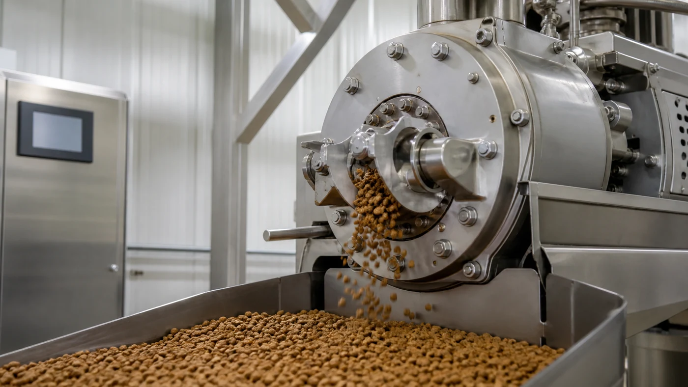
The die and cutter are where a conditioned pet food mass becomes a recognisable kibble. They determine the product's exit geometry, strand separation, cut length, surface appearance, and the first mechanical handoff to downstream drying. A stable die-and-cutter system is therefore not a cosmetic add-on to an extruder; it is a process interface that affects product consistency, dryer loading, fines, packaging appearance, and the practical range of products a factory can make.
A project should select this system from the intended product portfolio and operating window, not from one sample shape. Kibble size, cross-section, expansion, density, formula, moisture, temperature, line rate, cutter arrangement, drying route, cleaning method, and changeover frequency all matter. This guide explains the decisions that should be defined before specifying a dry pet food line.
Start with the finished product requirement
Describe each planned product family in measurable terms: shape, nominal dimensions, target piece weight where relevant, density range, visual appearance, texture, expected fines, coating route, packaging format, and intended production rate. State which characteristics are product requirements and which are design preferences. A round kibble, a ring, a bone-like profile, a pillow, or a treat can place different demands on the die, cutter, transfer, dryer, and cooler.
Shape is created by more than the hole pattern in a die plate. The product's formulation, grinding, hydration, preconditioning, extruder energy input, pressure, die geometry, discharge conditions, cutter operation, and downstream handling all influence the result. A die cannot correct an unstable upstream mass flow or a recipe that is outside its practical processing range.
The preconditioning-system guide explains why stable water, steam, mixing, and residence conditions are needed before the material enters extrusion. Those conditions should be part of the die-and-cutter specification because they directly influence how the product arrives at the die.
Understand the role of the die
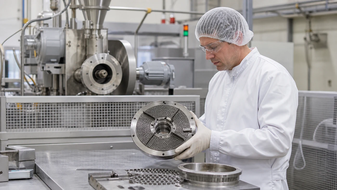
The die is the shaped restriction at the extruder discharge. Its flow passages and land geometry guide the cooked mass as it leaves the barrel. The die plate, inserts, face, heating or cooling provisions where used, seals, mounting, and access arrangement must work together with the extruder head. The exact construction is supplier- and application-specific, but the engineering question is consistent: how will this die deliver the intended product over the full approved rate and recipe range?
Die passage size and profile affect the exiting strand, pressure response, and sensitivity to wear or blockage. A complex shape can be commercially useful but may need more careful flow balancing, cleaning, handling, and start-up control than a simple round profile. Ask for a clear statement of what product assumptions the die design uses, including formula characteristics, throughput, pressure range, product temperature, and desired expansion.
Do not treat a die drawing as proof of product performance. Require product trials, representative samples, and documented acceptance measures. Official extrusion suppliers also present dies and knife heads as exchangeable product-format components, which reinforces the need to plan them as a controlled part of the production system rather than a one-time hardware purchase.
Specify cutter type and cutting geometry from the product route
At the die face, rotating knives or other cutting arrangements separate the emerging strands into individual pieces. Cutter speed, knife condition, clearance, blade geometry, mounting rigidity, strand distribution, and product flow all affect length consistency and the quality of the cut surface. The correct arrangement must suit the shape, the desired piece length, the product's exiting condition, and the speed range required by the factory.
A cutter should not be selected solely because it can run fast. A high cutter speed may be appropriate for a short product at a certain throughput, but it can also alter the appearance of the cut or create unnecessary mechanical demand if the die output is not stable. Conversely, an insufficient cutting speed or unsuitable knife arrangement can lead to inconsistent length, strand pulling, or product accumulation at the discharge.
Plan the handoff below the cutter as carefully as the cut itself. The product may be hot, expanding, and mechanically sensitive when it falls or transfers to a spreader, dryer belt, or conveyor. An uneven discharge can make downstream drying less uniform even when the individual pieces look acceptable at the die face.
Link die performance to expansion and density
Expansion and bulk density are outcomes of the complete extrusion process. They can be influenced by recipe composition, particle size, moisture, thermal and mechanical energy, pressure, die configuration, and discharge conditions. The die contributes to the final result, but it does not act independently of upstream preparation and extruder operation.
Define a sensible sampling plan for each product: measure piece dimensions, bulk density by an agreed method, visual condition, cut consistency, fines, moisture, and relevant downstream observations. Compare samples across start-up, stable production, low practical rate, high practical rate, and after a controlled change. The goal is to establish a repeatable operating window, not to claim that one hardware setting will always create the same product.
The broader pet food extrusion guide explains the relationship among formulation, conditioning, cooking, shaping, drying, and coating. The die-and-cutter review should use the same mass-flow and product-condition basis as that process plan.
Control strand distribution before it reaches the knives
Uniform cutting begins with uniform product flow across the die face. If one section of the die receives a different pressure or mass flow, strands can emerge at different speeds or with different expansion. The cutter then receives an uneven product pattern, and the difference can appear as variable length, malformed pieces, additional fines, or inconsistent loading on the receiving belt.
Review the extruder-head flow path, die support, insert layout, and discharge arrangement with the equipment supplier. Confirm how product rows will be distributed to the cutter and then to the next process step. For some product types, a controlled distributor or spreader is as important as the cutter itself because it prevents product from arriving in piles or gaps at the dryer inlet.
When the product portfolio includes multiple shapes, keep the required die-specific change parts, support arrangement, cutter settings, and receiving route documented by recipe. A changeover is only repeatable when the physical setup and its verified operating conditions are identified together.
Design for wear, inspection, and spare parts
Die passages and knife edges are working surfaces. Their service life depends on formula characteristics, abrasiveness, operating rate, temperature, material selection, cleaning method, alignment, and normal operating hours. Wear can show up as changing piece dimensions, a rough cut surface, irregular discharge, rising process demand, more fines, or a product that no longer matches its approved visual standard.
Set an inspection routine before wear becomes a production failure. The routine should identify the parts to inspect, the safe isolation method, allowable condition, measurement or visual criteria, cleaning process, reinstallation checks, and record of service history. Do not rely only on a calendar interval; pair planned intervals with actual product and process observations.
Maintain a project-specific spare-parts list. It should include the die plate or inserts, compatible knives, knife holders or fasteners where applicable, seals, tools, gauges, and any supplier-required change components. Label the parts by product configuration and revision. A spare die that cannot be confidently matched to its product and setup can create a prolonged, avoidable stoppage.
Keep product contact and sanitation practical
The die area can retain product at the die face, cutter housing, guards, discharge chutes, and adjacent supports. During a normal stop or product change, residue can affect the next run. The design must provide safe access for inspection, cleaning, removal, reassembly, and verification without forcing workers to reach through guarded equipment or work on a hot, pressurised system.
Define whether the line uses dry cleaning, controlled disassembly, or another approved method. Cleaning requirements must match the formula, hazard review, equipment materials, and factory conditions. Wet cleaning should not be assumed for a dry process without a clear drainage, drying, and restart plan. After cleaning or die replacement, confirm that all guards, covers, fasteners, and safety interlocks are restored before production resumes.
Plan product sequencing across the extrusion head, die, cutter, dryer feed, and downstream transfers. A precise cutter does not prevent carryover if product remains in an adjacent chute or spreader. The changeover route needs to be reviewed as one connected system.
Provide meaningful controls and operating records
The die-and-cutter area should be visible within the line's normal controls and operating records. Relevant inputs may include extruder rate, screw speed, torque, barrel temperatures, die pressure, cutter speed, drive status, guard or interlock status, receiving-conveyor readiness, and product recipe. The exact signals depend on the equipment design; their purpose is to give operators a clear view of whether product is reaching the cutter and the next process stage as expected.
Setpoints should be stored by verified product recipe, but they must not become an uncontrolled substitute for process observation. An operator still needs to check the cut, product flow, and downstream condition at start-up and after meaningful changes. A control system can record a cutter speed accurately while a worn knife or blocked die passage is changing the actual product.
Define the response to a downstream stop. If a dryer belt, spreader, or first conveyor is unavailable, the cutter and extruder must be brought to a controlled condition. The restart procedure should establish whether product at the die, on the receiving route, or in the first dryer zone needs inspection, segregation, or an approved disposition.
Size the receiving route and dryer interface
The cutter does not finish the job when the piece leaves the knife. A receiving conveyor, vibratory spreader, or dryer feeder may need to separate, distribute, and convey the product without piling, excessive drop height, or new breakage. The route should preserve the piece length and shape that the die-and-cutter system has created.
Dryer performance is affected by bed depth and product distribution. Uneven product loading can result in uneven residence time and airflow exposure. The pet food dryer guide covers the drying interface in more detail; the die-and-cutter specification should state the expected discharge pattern and the accepted receiving-belt load.
Review product temperature, expansion behaviour, discharge height, belt speed, guard design, fines removal, and the practical access required to inspect the first transfer. A compact line drawing can hide a difficult handoff, so this interface should be checked in layout and during site commissioning.
Plan changeovers as controlled product setups
A useful changeover procedure identifies more than the die plate. It lists the product recipe, die or insert identity, cutter configuration, knife type and condition, guard arrangement, receiving-conveyor setting, dryer feed configuration, target product observations, cleanout steps, and required verification samples. This reduces the chance that a correct die is paired with an incorrect knife, speed range, or downstream spreader setting.
Before changing a product, decide how the prior material will be removed, identified, or held. Record where product may remain in the extruder head, die, cutter, chute, receiving conveyor, dryer entry, and connected transfers. A controlled changeover is also an opportunity to inspect wear and to confirm that the next product's components are available before the line is opened.
For a factory with frequent shape changes, compare the time, labour, safety access, cleaning burden, spare-part inventory, and commissioning requirement for each proposed die-and-cutter package. The lowest equipment price is not necessarily the lowest cost of operating a diverse product portfolio.
Commission with representative product and agreed acceptance criteria
Factory acceptance testing can verify mechanical construction, supplied parts, rotation, guards, instrumentation, documentation, and basic controls. Site commissioning must confirm the system with the actual formulation and product route. Test the approved die and cutter at representative conditions, including start-up, normal operation, the practical rate range, planned stops, cleaning or changeover, and sustained product flow to downstream equipment.
Agree in advance how the site will evaluate the result. Useful measures can include piece dimensions, length distribution, bulk density, visual appearance, cut surface, fines, product flow to the dryer, alarm response, and condition after drying and packing. The method, sample location, batch identity, time, and acceptance responsibility should be documented so a result can be interpreted consistently.
Do not promise a universal die life, cut length, density, or production rate in a generic equipment request. Those values depend on the project's formulation, product, operating window, equipment design, and acceptance plan. A defensible proposal makes its assumptions visible and provides a route to validate them.
Information to include in a die-and-cutter system request
- planned product families, drawings or samples where available, target shape, nominal dimensions, density range, texture, visual requirements, and packaging format;
- formula characteristics, meal particle size, conditioning target, expected extrusion rate, moisture basis, and operating range for each product family;
- required die types, inserts, cutter configuration, changeover frequency, trial expectations, and acceptable product variation or fines;
- extruder-head interface, product distribution, receiving conveyor or dryer-feed interface, drop heights, guards, access, and layout constraints;
- product-contact materials, cleaning and sanitation method, residue and changeover requirements, safe isolation, and required tools;
- control signals, recipe records, alarms, interlocks, downstream-stop response, manuals, training, spare parts, and wear-inspection criteria;
- FAT, site commissioning, representative product trials, sample plan, acceptance measures, and responsibility for confirming the final configuration.
Select a product-format system, not just a die plate
A capable pet food die-and-cutter system is built around the actual product portfolio. It connects stable upstream preparation with controlled extrusion discharge, consistent cutting, a suitable dryer interface, hygienic access, documented changeover, planned maintenance, and meaningful commissioning.
PetFactorySystem.com can support product-route definition, die-and-cutter specification, layout interfaces, spare-parts planning, changeover logic, control requirements, and site acceptance planning for a dry pet food factory system.
Review the related factory system
Compare the production route, equipment package, layout assumptions, capacity target, and operating requirements before confirming a factory plan.