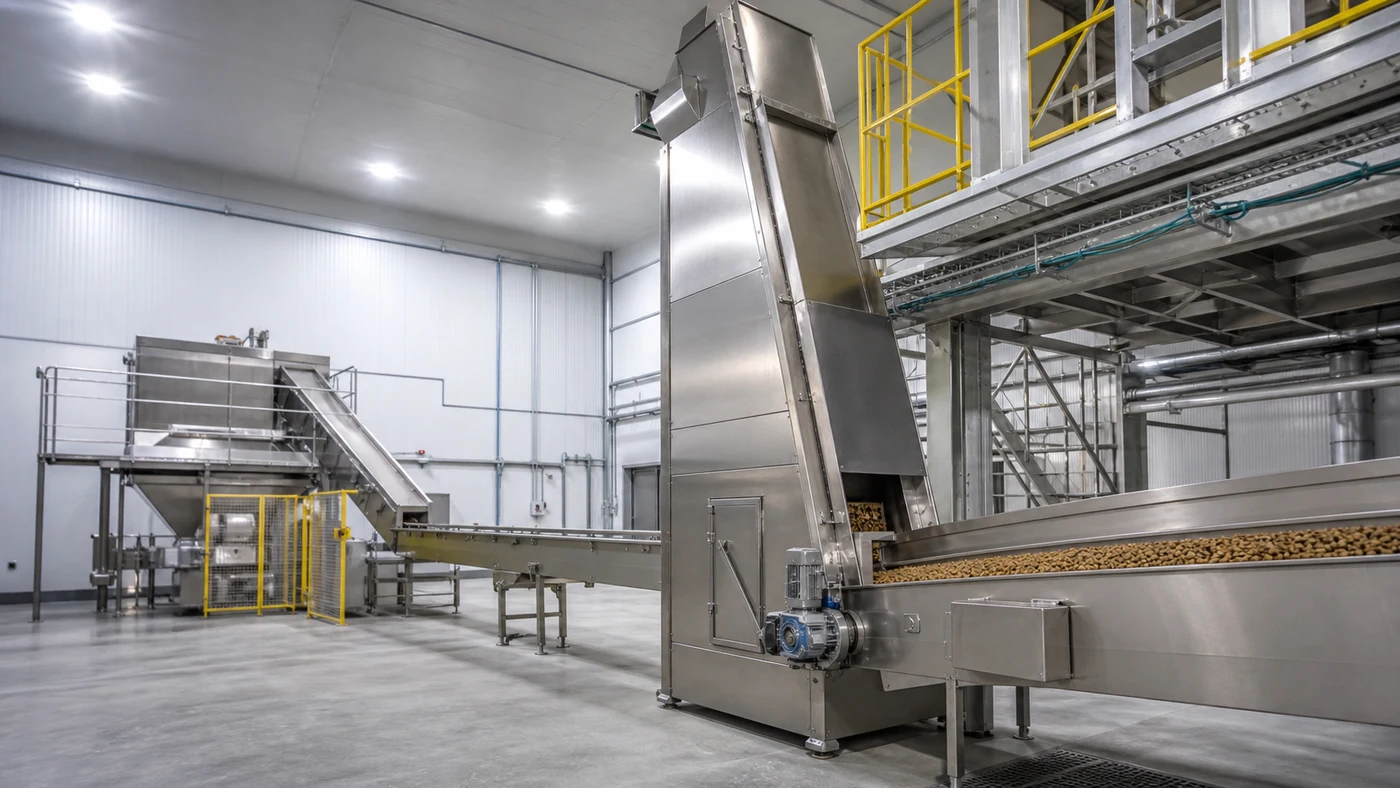
A pet food conveying system is the connection between every major process step. It moves meal into grinding and mixing, carries conditioned material into extrusion, transfers hot or cooled kibble between downstream stages, and delivers finished product to inspection and packing. When those transfers are treated as an afterthought, the result can be broken kibble, dust, product hold-up, cross-contact risk, or a line that cannot sustain its intended output.
The right design starts with the material state at each handoff, not with a catalogue list of conveyors. A fine dry meal, a warm conditioned feed, freshly extruded pieces, dry fragile kibble, coated kibble, and packed product each impose different handling requirements. The route should be specified as part of the complete factory system.
Map the material route before selecting equipment
Start with a route drawing that follows every product stream from receiving to final pack. For each handoff, record product form, bulk density, temperature, moisture condition, fat or coating status, particle size, likely fines, minimum and maximum rate, campaign duration, and the next process step. Also record the direction of travel, elevation change, horizontal distance, required buffer time, available building space, and whether the route must be enclosed.
This exercise usually reveals that a single generic conveyor type is not suitable for the whole factory. Bucket elevators, belt conveyors, chain conveyors, screw conveyors, vibratory feeders, pneumatic transfer, bins, valves, and chutes each have different strengths. The selection must be based on the product and the exact duty. Established feed-processing suppliers similarly combine elevators, belt, chain, and screw conveyors according to the material and plant interface rather than applying one universal device.
Include non-routine states in the route map. Start-up, low-rate operation, a coater stop, a bagger stop, product changeover, cleaning, and restart are when material can remain in equipment or take an unintended path. A reliable factory plan defines what happens to the material in those moments before the equipment is purchased.
Separate ingredient handling from finished-kibble handling
Upstream dry ingredients are often powders, meals, grains, or small particulates. They may need controlled dosing, dust containment, magnetic protection, sifting, and a route that limits segregation. Downstream dry kibble is a finished, shaped product that can be damaged by high drops, unsuitable flights, high-speed impacts, excessive vibration, or abrupt transitions. Its surface condition can change again after oils and palatants are applied.
Do not size one conveying route from the finished-line capacity and assume the same value applies upstream. Ingredient flow is often affected by batch sequence, weighing, grinding throughput, and buffer strategy. Final-product flow must also account for the mass added during coating, packing-machine availability, inspection equipment, and finished-goods accumulation.
The upstream route should be reconciled with the grinding system and particle-size plan. A poorly controlled transfer before or after milling can change the feed consistency seen by the mixer, even when the mill itself is correctly specified.
Choose a conveyor by product condition and route, not nameplate capacity
A bucket elevator is a practical vertical transfer option for many grains, meals, pellets, and kibbles when its buckets, belt or chain, inlet, discharge, access, and speed suit the material. A belt conveyor may be appropriate for a long, gentle horizontal route. A chain conveyor can suit enclosed horizontal movement of some bulk products. Screw conveyors are often useful for controlled discharge or short material transfers, but their use must be checked carefully for product sensitivity, cleanout, and possible carryover. Pneumatic conveying can be useful for some powders and controlled material transfers, but it should not be assumed to be the best choice for every fragile or coated kibble route.
For each option, compare the actual inlet condition, elevation, route length, rate range, product integrity, enclosure, sanitation access, cleanout, power use, maintenance, and interface with the next machine. A capacity figure only means something when the product, fill level, speed, height, and route geometry are defined. Ask suppliers to state those assumptions rather than comparing a single tonnes-per-hour number.
There is also a difference between moving product and feeding a process. A conveyor that can transport a material at a high rate may not deliver it evenly enough to a dryer, cooler, coater, or packaging hopper. Where bed depth or feed consistency matters, the transfer device and its controls must be selected together with the receiving process.
Protect kibble at transfer points
Many fines are created where one machine hands product to another, not in the middle of a straight conveyor. Common risk points include a cooler discharge, a bucket-elevator inlet, an elevator head, a diverter, a long vertical drop, a narrow chute, a sharp change in direction, and a poorly matched conveyor speed. The result can be visible breakage, extra fines at the bagger, unstable coating distribution, or a product that no longer meets its intended appearance.
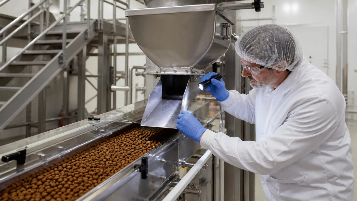
Design the chute as a product-contact component. Check its angle, radius, cross-section, mounting, access covers, joints, inspection points, and the distance from the exit to the receiving belt or hopper. The objective is controlled flow without ledges that trap product or abrupt impacts that fracture it. A transparent guard may help observation, but it does not replace a safe cleanout and inspection arrangement.
Evaluate breakage with representative product and a sustained run. Samples should be taken before and after critical transfers, then compared for fines, broken pieces, and effect on downstream equipment. This is more useful than accepting an equipment route based only on empty-machine operation.
Plan the hot and warm product route deliberately
Product leaving extrusion, drying, cooling, or coating is not interchangeable. Temperature, surface condition, moisture, and fragility can change across a short route. A long enclosed conveyor or high-fill bin can retain heat. An uncontrolled exposure to humid room air can create a different problem. The route after each thermal step must be reviewed with the product condition that actually leaves that step.
The preconditioning-system guide covers the short, controlled path from steam and water conditioning into the extruder. At the other end of the line, the kibble cooling guide explains why cooling and packaging interfaces need a shared acceptance condition. Conveying joins those process controls together.
For a route after coating, evaluate product temperature, fat or palatant pickup, surface tackiness, discharge behaviour, and the opportunity for product to build up inside a transfer. The coating-system guide provides the process context; the material-handling route must then preserve the condition created by the coater.
Provide buffer capacity without losing product control
Surge bins and accumulators can decouple two machines that do not stop or restart at the same time. They are useful only when the product can remain in the buffer for a defined period without unacceptable temperature change, breakage, segregation, carryover, or quality risk. A bin is not a neutral storage space simply because it has a large volume.
Define usable volume, not just geometric volume. The usable range depends on product bulk density, hopper angle, internal flow pattern, level controls, discharge equipment, bridging tendency, and the required emptying or cleanout method. Check whether the product will flow first-in first-out or whether pockets of older material can remain in corners or on internal surfaces.
Specify the control response when the packing line stops. The upstream process may need to slow, reduce feed, continue a controlled discharge, or stop in a defined sequence. The operating procedure should identify the material that remains in each buffer and the restart checks required before product is released to pack.
Control dust, product loss, and air movement
Dry ingredient handling can generate dust at receiving hoppers, screens, bins, transfer chutes, and conveyor inlets. Fines from finished kibble can also become airborne during impacts and high-velocity drops. Equipment enclosure, aspiration points, duct design, access, housekeeping, and the wider site dust-hazard assessment must be planned together. An extraction point that captures material but creates an uncontrolled product-recovery stream has not solved the process problem.
Use enclosed transfers where the product and process require them, while still providing access for inspection and cleanout. Make sure air entering or leaving a product route does not carry dust into clean packing zones or pull unwanted room air through a warm product stream. The building ventilation and dust-collection concept must be coordinated with the process layout.
A material route should include practical recovery and reconciliation logic. If a filter, screen, magnet, metal detector, or inspection system rejects material, operators must know where that material goes, how it is identified, and when it may or may not be returned to the process.
Design sanitation and changeover into the route
Dry-process equipment can retain product at boot sections, screw flights, elevator buckets, chute ledges, diverters, bin corners, conveyor returns, and inspection doors. Residue matters for flavour, colour, protein, formula, and label control. It also makes an unexplained line loss harder to investigate.
Before installation, identify every product-contact surface and every place where product can remain after a normal stop. Define access panels, removable sections, safe isolation points, tool access, lighting, collection trays where needed, and the cleaning or flush method. The method should match the site's hazard and quality review. Wet cleaning in a dry area creates its own drainage, drying, and restart requirements and should not be introduced casually.
Changeover planning should cover the connected route, not only the major process machine. The factory hygiene and sanitation plan should align route inspection, product sequencing, residue management, verification, and records.
Make capacity calculations across the full line
Every conveyor must support the intended factory output, but the highest rated component does not determine line capacity. A line can be limited by a slow transfer, a small hopper, a restricted diverter, a screen, a metal detector, a bagger, or the time required to empty a buffer before a product change. The actual rate must be reconciled from raw-material intake to finished-product discharge.
Use a common capacity basis: dry ingredient rate, extruder feed rate, dryer discharge rate, coated-product rate, or packed-product rate. State the moisture and liquid-addition assumptions wherever they change mass flow. Then check the design at minimum, normal, and maximum practical output. This is especially important when a new product has different density or shape from the first product used to select the route.
Use a capacity and line-balancing review to identify the real constraint and document the buffer strategy around it. The goal is a controlled operating envelope, not a collection of individually oversized machines.
Place instruments and controls at meaningful handoffs
Useful conveying controls may include motor status, speed, level, blockage detection, belt or chain monitoring where applicable, gate position, pressure or airflow, product temperature, downstream-ready signals, and emergency or safety interlocks. The exact instrumentation depends on the route. Its purpose is to show operators whether material is moving as intended and to protect the product when another part of the line changes state.
Build a control narrative for each critical stoppage. If the coater stops, should the upstream cooler discharge, hold product, or reduce feed? If the bagger stops, what buffers are available and how is their residence time managed? If a level sensor fails, what is the safe and quality-protective response? These decisions should be agreed before commissioning, not improvised during the first production interruption.
Recipe and batch identification should follow the product through the route. This gives the site a practical way to investigate an issue at packaging back through coating, cooling, and the upstream product stream.
Check layout, access, and maintenance before the steel is fixed
Conveyors seem compact on a process flow diagram, but they require headroom, support steel, platform access, guard clearance, maintenance space, drive removal paths, cleaning access, cable routes, aspiration duct space, and safe working positions. A vertical elevator also needs space at the boot and head for inspection and service. These requirements can determine building height and process-floor arrangement.
Review the physical layout in three dimensions before fabrication. Confirm the route does not block a forklift lane, prevent access to a dryer or coater, place a cleaning task above an open product zone, or require a worker to reach over a moving conveyor. Where equipment passes through floors or walls, define sealing, support loads, fire and building interfaces, and access on both sides.
A layout review should include operators, maintenance, quality, safety, and cleaning personnel. They will identify access constraints that a process drawing alone cannot show.
Commission the route with real product
Factory acceptance testing should verify construction, drives, guards, sensors, controls, access, and documentation. Site testing must prove the route with representative products and operating conditions. Test start-up, normal rate, low rate, maximum practical rate, planned stops, changeover, cleanout, and restart. Include samples for fines and breakage around the transfers that are most likely to damage product.
Confirm actual flow direction, discharge consistency, buffer behaviour, alarm response, dust control, product identification, and access procedures. If one equipment package is changed after commissioning, recheck the adjacent handoffs. A new conveyor speed, chute, bin, or packing machine can change how the previous equipment performs.
What to include in a pet food conveying-system request
- product families and states at every handoff: meal, conditioned feed, hot product, dry kibble, coated kibble, or packed product;
- minimum, normal, and maximum rate on a clearly stated mass basis, plus density, particle size, temperature, moisture, and coating condition;
- route drawing with inlet and outlet elevations, horizontal distance, required buffers, available building dimensions, and adjacent equipment;
- acceptable fines and breakage, product-contact materials, enclosure, cleanout, access, sanitation, and product-changeover requirements;
- dust-collection, air, electrical, structural, maintenance, guard, platform, and safety-interlock interfaces;
- controls, level strategy, material tracking, response to upstream and downstream stops, alarms, records, and operator instructions;
- FAT and site acceptance tests using representative products, including sustained-rate, transfer, breakage, cleanout, and restart checks.
Build a controlled route, not a chain of isolated machines
A good pet food conveying system protects the product condition created at each process stage and delivers it consistently to the next one. It combines suitable equipment, gentle transfer points, defined buffer behaviour, cleanable construction, dust control, practical access, and controls that respond to real line events.
PetFactorySystem.com can develop a material-flow map, equipment specification, layout interfaces, buffer strategy, sanitation access, control narrative, and commissioning plan for a dry pet food line. A useful technical review begins with the product route, capacity range, factory location, and available layout information.
Review the related factory system
Compare the production route, equipment package, layout assumptions, capacity target, and operating requirements before confirming a factory plan.